PRACTICAL TRAINING
AT
Centre for Railway Information Systems,
INDIAN RAILWAYS, DELHI
On
“LOCAL AREA NETWORK”
GENESIS OF INDIAN RAILWAYS
The story of the Indian Railways (IR) is not just a saga of mundane statistics and miles of rolling stock. It is the glorious tale of a pioneering institution that has blazed a trail for nearly a century and a half, making inroads into far-flung territory and providing a means of communication.
Indian
Railway is one of India's most effective networks that keep together the
social, economical, political and cultural fabric of the country intact. Be
it cold, mountainous terrain or the long stretches through the Rajasthan
desert, Indian Railways cover the vast expanse of the country from north to
south, east to west and all in between.
More than a
hundred years ago, on the 16 April 1853, a red-letter day appeared in the
glorious history of the Indian Railways. On the day, the very first railway
train in India ran over a stretch of 21 miles from Bombay to Thane. This
pioneer railway train consisting of 14 railway carriages carrying about 400
guests, steamed off at 3:30 pm amidst the loud applause of a vast multitude
and to the salute of 21 guns. It reached Thane at about 4.45 pm. The guests
returned to Bombay at 7 pm on the next day, that is, April 17. On April 18,
1853, Sir Jamsetjee Jeejeebhoy, Second Baronet, reserved the whole train and
traveled from Bombay to Thane and back along with some members of his family
and friends.
This
was the humble beginning of the modern Indian Railway system known today for
its extraordinary integration of high administrative efficiency, technical
skill, commercial enterprise and resourcefulness. Today the Indian Railway (IR)
is one of the most specialized industries of the world.
OTHER MILESTONES
Under the
British East India Company's auspices, the Great Indian Peninsula Railway
Company (GIPRC) was formed on July 15, 1844. Events moved at a fast pace. On
October 31, 1850, the ceremony of turning the first sod for the GIPRC from
Bombay to Kalyan was performed. The opening ceremony of the extension to
Kalyan took place on May 1, 1854. The railway line from Kalyan to Khopoli
was opened on May 12, 1856. It was further extended to Poona on June 14,
1858 when the traffic was opened for public use.
In the eastern part of India, the first passenger train steamed
out of Howrah station for Hooghly, a distance of 24 miles, on August 15,
1854. This marked the formation of the East Indian Railway.
This was
followed by the emergence for the Central Bengal Railway Company. These
small beginnings multiplied and by 1880, the IR system had a route mileage
of 9,000 miles in India.
The Northeastern Railway also developed rapidly. On October 19,
1875, the train between Hathras Road and Mathura Cantonment was started. By
the winter of 1880-81, the Kanpur-Farukhabad line became operational and
further east, the Dibrugarh-Dinjan line became operational on August 15,
1882.
In South India, the Madras Railway Company opened the first railway
line between Veyasarpaudy and the Walajah Road (Arcot) on July 1, 1856. This
63-mile line was the first section, which eventually joined Madras and the
west coast. On March 3, 1859, a length of 119 miles was laid from Allahabad
to Kanpur.
In
1862, the railway line between Amritsar and Attari was constructed on the
Amritsar-Lahore route.
Some of the trains started by the British are still in existence.
The Frontier Mail is one such train. It was started on September 1, 1928 as
a replacement for the Mumbai-Peshawar mail. It became one of the fastest
trains in India at that time and its reputation in London was very high.
The Kalka Mail from Howrah to Kalka was introduced with the
specific goal of facilitating the annual migration of British officials,
their families and their retinue of servants and clerks from the imperial
capital at Calcutta to the summer capital in Shimla. From Kalka, there was
the remarkable toy train service to Shimla. Plans for this narrow-gauge
train had started as early as 1847, but it was at the intervention of the
Viceroy, Lord Curzon, that work actually began. Hence this train service was
also known as the Viceroy's Toy Train. In order to prevent any head-on
collisions on the single-track sections of this railway service, the Neals
Token System has been used ever since the train was inaugurated. The train
guards exchange pouches containing small brass discs with staff on the
stations en route. The train driver then puts these discs into special
machines, which alert the signals ahead of their approach. The Darjeeling
toy trains, the Matheran toy train from Neral to Matheran, the Nilgiri Blue
Mountain Railway are other engineering marvels running on routes designed
and built by the British. Trains like the Deccan Queen from Bombay to
Secunderabad and the Grand Trunk Express from Delhi to Madras are some other
prominent trains initiated by the British.
With the advancement in the railway system, electrifying railway
lines began side by side, and it was in 1925, that the first electric train
ran over a distance of 16 km from Victoria Terminus to Kurala.
THE NEED FOR A RAILWAY NETWORK
The British
rule in India was governed by three principal considerations to expand the
IR system. These were the commercial advantages, the political aspect and
even more importantly, the inexorable imperial defense of India against the
possible military attacks from certain powerful countries showing signs of
extending their orbit of influence into Central Asia.
RECENT DEVELOPMENTS
Now, to
further improve upon its services, the Indian Railways have embarked upon
various schemes, which are immensely ambitious. The railway has changed from
meter gauge to broad gauge and the people have given it a warm welcome. Now,
there are the impressive-looking locomotives that haul the 21st-century
harbingers-the Rajdhanis and Shatabdis-at speeds of 145 kmph with all
amenities and comfort. With these, the inconvenience of changing to a
different gauge en route to a destination will no longer be felt.
The Research, Designing, and Standardizing Organization at Lucknow-the
largest railway research organization in the world-was constituted in 1957.
It is constantly devising improvements in the signaling systems, track
design and layout, coach interiors for better riding comfort and capacity,
etc., along with improvements in locomotives. Improvements are being planned
by engineers. The workshops of the railways too have been given new
equipment to create sophisticated coaches at Perambur and Kapurthala and
diesel engine parts at Patiala. Locomotives are being made at Chittaranjan
and Varanasi. This is in sharp contrast to the earlier British conviction
that only minor repairs would be possible in India, so all spare parts
including nuts and bolts for locomotives would have to be imported from
England.
More trains and routes are constantly being added to the railway
network and services. The British legacy lives on in our railway system,
transformed but never forgotten. Long live the Romance of the Rails!
The network of lines has grown to about 62,000 kilometers. But, the
variety of Indian Railways is infinite. It still has the romantic toy trains
on narrow gauge hill sections, meter gauge beauties on other and broad gauge
bonanzas as one visits places of tourist interest courtesy Indian Railways!
They are an acknowledgement of the Railways that tourism as an industry has
to be promoted and that India is full of unsurpassed beauty.
The Calcutta Metro is a fine example of highly complex engineering
techniques being adopted to lay an underground railway in the densely
built-up areas of Calcutta city. It is a treat to be seen. The Calcuttans
keep it so clean and tidy that not a paper is thrown around! It only proves
the belief that a man grows worthy of his superior possessions. Calcutta is
also the only city where the Metro Railway started operating from September
27, 1995 over a length of 16.45 km. There is also a Circular Railway from
Dum Dum to Princep Ghats covering 13.50 km to provide commuter trains.
RAIL
MUSEUM
A
number of the private saloons of erstwhile princes along with other rare
railways relics can be viewed today at the Rail Transport Museum in New
Delhi, which was set up in the year 1977 to display the glorious heritage of
IR tracing its development from its beginning.
The museum has a collection of 75 real exhibits, including
vintage steam, diesel and electric locomotives, coaches and wagons dating
back to 1855. The collection also includes the steam locomotive called Fairy
Queen of 1855, the saloons of the erstwhile maharajas such as the unique
Patiala State Monorail Train way of 1907. Railway staff is available at the
site to conduct the visitors, provide written material, and there are
special facilities for the handicapped and the blind. The museum is located
in the setting of a spruce garden of flowers, shrubs, trees, and lawns. The
museum attracts 300,000 visitors each year from abroad and from various
parts of India.
HELPLINES
In time of war and natural disasters, the railways play a major role.
Whether it was the earthquake of 1935 in Quetta (now in Pakistan) or more
recently in Latur in Maharashtra, it is the railways that muster their
strength to carry the sick and wounded to hospitals in nearby towns and to
the people of the affected areas. In rehabilitation and reconstruction, too,
their role is vital.
During the Japanese war, the Indian Railways added further laurels
to their record as they extended the railway line right up to Ledo in the
extreme northeastern part of Assam and thus enabled the Allied forces under
General Stillwell to combat the Japanese menace. In fact, several townships
in Assam like Margherita and Digboi owe their origin to the endeavors of the
Indian Railways. It was the Assam Railway and Trading Company that opened up
the isolated regions of Assam with the laying of the railway lines and thus
providing the lifeline to carry coal, tea, and timber out of the area and
bring other necessary commodities to Assam and the adjoining countryside.
Now, the Indian Railways system is divided into 9 zonal railways, a
metro railway, Calcutta, the production units, construction organizations,
and other railway establishments. Usually, a general manager heads each
division presented in the table below.
SCOPE OF TRAINING
After achieving the proper goal of life an Engineer has enter in professional life. According to this life he has to serve an industry, may be public or private sector or self-own. For the efficient work in the field he must be well aware of practical knowledge as well as theoretical knowledge. Since we belong to the electronics field it is really helpful to take training at a place that clears the doubts and inquisitively regarding the looking-simple phenomenon.
The training at Indian Railways is related to many fields of engineering; it is one of the fastest growing industry in the world. Training at Indian Railways not only improves your subject theoretical knowledge but also improve the practical skill.
I worked there on study project named “Local Area Networks”. It was a great learning experience there.
LEARNING OBJECTIVES
Short term
The main short-term advantage after completing the training was an idea of the industrial environment, the strict and disciplined schedule of the company. This helped me a lot to build inside me the zeal to learn more, to be highly precise and accurate in my working. It helped in understanding the relationship that should be maintained between an officer and a worker, officer and a trainee and also between worker and trainee. The good and learning environment helped a lot to understand the difficulties or problems faced during the project completion. The short term learning objective were to just to see how things works and how communication is possible
Long term
The introduction to an official as well as industrial environment would help a lot in future to work in a company concerning to the field of communication, to cope up with the increasing competition in the market also it would help in building up a good relationship between myself and the colleagues. This industrial training has helped me a lot to stand in the corporate world.
METHODOLOGY
In training at Indian Railways emphasis was given on the latest technologies and the basic fundamentals of communication which are required to cope up with the diverted needs of communication and study about the present day services provided by Indian Railways. We were given thorough instructions and knowledge about almost all the aspects of Networking. The officers also made us familiar with the various equipments being used.
CONTENTS
1) Networking
2) History of LAN
3) OSI reference model
4) Protocols
5) IP Address
6) LAN Topologies
7) Types of LAN Technology
8) LAN Devices
NETWORKING
Computer networking is an integral part of
business today. A network is a group of computers, printers, and other
devices that are connected together with cables. Information travels over
the cables, allowing network users to exchange documents & data with each
other, print to the same printers, and generally share any hardware or
software that is connected to the network.
Each computer, printer, or other peripheral device that is connected
to the network is called a node. Networks can have tens, thousands, or even
millions of nodes.
Local Area Networks (LANs):
A network is any collection of independent computers that exchange information with each other over a shared communication medium. Local Area Networks or LANs are usually confined to a limited geographic area, such as a single building or a college campus. LANs can be small, linking as few as three computers, but can often link hundreds of computers used by thousands of people. The development of standard networking protocols and media has resulted in worldwide proliferation of LANs throughout business and educational organizations
Wide Area Networks (WANs):
Often elements of a network are widely separated
physically. Wide area networking combines multiple LANs that are
geographically separate. This is accomplished by connecting the several LANs
with dedicated leased lines such as a T1 or a T3, by dial-up phone lines
(both synchronous and asynchronous), by satellite links and by data packet
carrier services. WANs can be as simple as a modem and a remote access
server for employees to dial into, or it can be as complex as hundreds of
branch offices globally linked. Special routing protocols and filters
minimize the expense of sending data over vast distances.
HISTORY OF LAN
In the days before personal computers, a sight might have just one central computer, with users acessing this via computer terminals over simple low-speed cabling.The first LANs were created in the late 1970s and used to create high speed links between several large central computers at one site. Of many competing systems created at this time, Ethernet and ARCNET were the most popular.
The growth of CP/M and then DOS based personal computer meant that a single site began to have dozens or even hundreds of computers. The initial attraction of networking these was generally to share disk space and laser printers, which were both very expensive at the time. There was much enthusiasm for the concept and for several years from about 1983 onward computer industry pandits would regularly declare the coming year to be “the year of the LAN”
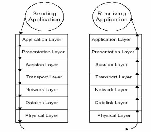
OSI REFERENCE MODEL
The OSI reference model consists of seven layers, each of which can (and typically does) have several sub layers. The upper layers of the OSI reference model (application, presentation, session, and transport—Layers 7, 6, 5, and 4) define functions focused on the application. The lower three layers (network, data link, and physical—Layers 3, 2, and 1) define functions focused on end to end delivery of the data.
OSI Reference Model:-
• The model was developed by the International Organisation for Standardisation (ISO) in 1984. It is now considered the primary Architectural model for inter-computer communications.
• The Open Systems Interconnection (OSI) reference model is a descriptive network scheme. It ensures greater compatibility and interoperability between various types of network technologies.
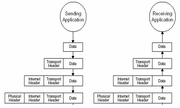
• The OSI model describes how information or data makes its way from application programmes (such as spreadsheets) through a network medium (such as wire) to another application programme located on another network.
• The OSI reference model divides the problem of moving information between computers over a network medium into SEVEN smaller and more manageable problems.
This separation into smaller more manageable functions is known as layering.
|
OSI Layer Name |
Functional Description |
Examples |
|
Application (Layer 7) |
Interface between network and application software |
Telnet, HTTP
|
|
Presentation(Layer 6) |
How data is presented Special processing, such as encryption |
JPEG, ASCII, EBCDIC
|
|
Session (Layer 5) |
Keeping data separate from different applications |
Operating systems and application access scheduling |
|
Transport (Layer 4) |
Reliable or unreliable delivery Multiplexing |
TCP, UDP, SPX
|
|
Network (Layer 3) |
Logical addressing, which routers use for path determination |
IP, IPX
|
|
Data link (Layer 2) |
Combination of bits into bytes, and bytes into frames |
Access to the media using MAC address Error detection and error recovery |
|
Physical (Layer 1) |
Moving of bits between devices Specification of voltage, wire speed, and cable pinouts |
EIA/TIA-232, V.35
|
LAYER 7: APPLICATION
• The application layer is the OSI layer that is closest to the user.
• It provides network services to the user’s applications.
• It differs from the other layers in that it does not provide services to any other OSI layer, but rather, only to applications outside the OSI model.
• Examples of such applications are spreadsheet programs, word processing programs, and bank terminal programs.
• The application layer establishes the availability of intended communication partners, synchronizes and establishes agreement on procedures for error recovery and control of data integrity.
LAYER 6: PRESENTATION
• The presentation layer ensures that the information that the application layer of one system sends out is readable by the application layer of another system.
• If necessary, the presentation layer translates between multiple data formats by using a common format.
• Provides encryption and compression of data.
• Examples: - JPEG, MPEG, ASCII, EBCDIC, HTML.
LAYER 5: SESSION
• The session layer defines how to start, control and end conversations (called sessions) between applications.
• This includes the control and management of multiple bi-directional messages using dialogue control.
• It also synchronizes dialogue between two hosts' presentation layers and manages their data exchange.
• The session layer offers provisions for efficient data transfer.
• Examples: - SQL, ASP (AppleTalk Session Protocol).
LAYER 4: TRANSPORT
• The transport layer regulates information flow to ensure end-to-end connectivity between host applications reliably and accurately.
• The transport layer segments data from the sending host's system and reassembles the data into a data stream on the receiving host's system.
• The boundary between the transport layer and the session layer can be thought of as the boundary between application protocols and data-flow protocols. Whereas the application, presentation, and session layers are concerned with application issues, the lower four layers are concerned with data transport issues.
• Layer 4 protocols include TCP (Transmission Control Protocol) and UDP (User Datagram Protocol).
LAYER 3: NETWORK
• Defines end-to-end delivery of packets.
• Defines logical addressing so that any endpoint can be identified.
• Defines how routing works and how routes are learned so that the packets can be delivered.
• The network layer also defines how to fragment a packet into smaller packets to accommodate different media.
• Routers operate at Layer 3.
• Examples: - IP, IPX, AppleTalk.
LAYER 2: DATA LINK
• The data link layer provides access to the networking media and physical transmission across the media and this enables the data to locate its intended destination on a network.
• The data link layer provides reliable transit of data across a physical link by using the Media Access Control (MAC) addresses.
• The data link layer uses the MAC address to define a hardware or data link address in order for multiple stations to share the same medium and still uniquely identify each other.
• Concerned with network topology, network access, error notification, ordered delivery of frames, and flow control.
• Examples: - Ethernet, Frame Relay, FDDI.
LAYER 1: PHYSICAL
• The physical layer deals with the physical characteristics of the transmission medium.
• It defines the electrical, mechanical, procedural, and functional specifications for activating, maintaining, and deactivating the physical link between end systems.
• Such characteristics as voltage levels, timing of voltage changes, physical data rates, maximum transmission distances, physical connectors, and other similar attributes are defined by physical layer specifications.
• Examples: - EIA/TIA-232, RJ45, NRZ.
ISO OPEN SYSTEM INTERCONNECTION (OSI) MODEL
PROTOCOLS
After a physical connection has been established, network protocols define the standards that allow computers to communicate. A protocol establishes the rules and encoding specifications for sending data. This defines how computers identify one another on a network, the form that the data should take in transit, and how this information is processed once it reaches its final destination. Protocols also define procedures for determining the type of error checking that will be used, the data compression method, if one is needed, how the sending device will indicate that it has finished sending a message, how the receiving device will indicate that it has received a message, and the handling of lost or damaged transmissions or "packets".
The main types of network protocols in use today are: TCP/IP (for UNIX, Windows NT, Windows and other platforms); IPX (for Novell NetWare); DECnet (for networking Digital Equipment Corp. computers); AppleTalk (for Macintosh computers), and NetBIOS/NetBEUI (for LAN Manager and Windows NT networks)
TCP/IP:
TCP/IP encompasses a lot of smaller protocols, the Transmission Control Protocol and the Internet Protocol. TCP performs only part of the functions necessary to deliver the data between applications, and the role that it plays is directed toward providing services for the applications that sit at the endpoint computers.
TCP Functions
|
Function |
Description
|
|
Multiplexing |
Function that allows receiving hosts to decide the correct application for which the data is destined, based on the port number. |
|
Error recovery (reliability) |
Process of numbering and acknowledging data with sequence and acknowledgment header fields |
|
Flow control using windowing |
Process that uses window sizes to protect buffer space and routing devices |
|
Connection establishment and termination |
Process used to initialize port numbers and sequence and acknowledgement fields |
|
Ordered data transfer |
Continuous stream of bytes from upper-layer process that is “segmented” for transmission |
USER DATAGRAM PROTOCOL (UDP):
UDP provides a service for applications to exchange messages. Unlike TCP,
UDP is connectionless and provides no reliability, no windowing, and no function to ensure that the data is received in the order in which it was sent. However, UDP provides some functions of TCP, such as data transfer and multiplexing, and it does so with fewer bytes of overhead in the UDP header. The only difference in UDP (compared to TCP) sockets is that, instead of designating TCP as the transport protocol, the transport protocol is UDP. UDP data transfer differs from TCP data transfer in that no reordering or recovery is accomplished. Applications using UDP are tolerant of the lost data, or they have some application mechanism to recover lost data. For example, DNS requests use UDP because the user will retry an operation if the DNS resolution fails. The Network File System (NFS) performs recovery with application layer code, so UDP features are acceptable to NFS.
COMPARISON BETWEEN TCP AND UDP:
|
Function |
Description (TCP) |
Description (UDP) |
|
Data transfer |
This involves a continuous stream of ordered data. |
This involves message (datagram) delivery. |
|
Multiplexing |
Receiving hosts decide the correct application for which the data is destined, based on the port number. |
Receiving hosts decide the correct application for which the data is destined, based on the port number. |
|
Reliable transfer |
Acknowledgment of data uses the sequence and acknowledgment fields in the TCP header |
This is not a feature of UDP. |
|
Flow control |
This process is used to protect buffer space and routing devices. |
This is not a feature of UDP. |
|
Connections |
This process is used to initialize port numbers and other TCP header fields. |
DP is connectionless. |
IP ADDRESS
An IP address (Internet Protocol address) is a unique number that devices use in order to identify and communicate with each other on a computer network utilizing the Internet Protocol standard (IP). Any participating network device — including routers, computers, time-servers, printers, Internet fax machines, and some telephones — must have its own unique address.
DYNAMIC AND STATIC IP ADDRESSES:
IP addresses may either be assigned permanently (for example, to a server which is always found at the same address) or temporarily from a pool of available addresses.
Dynamic IP address:
Dynamic IP addresses are issued to identify non-permanent devices such as personal computers or clients. Internet Service Providers (ISPs) use dynamic allocation to assign addresses from a small pool to a larger number of customers. This is used for dial-up access, WiFi and other temporary connections, allowing a portable computer user to automatically connect to a variety of services without needing to know the addressing details of each network.
Static IP address:
Static IP addresses are used to identify semi-permanent devices with constant IP addresses. Servers typically use static IP addresses. The static address can be configured directly on the device or as part of a central DHCP configuration which associates the device's MAC address with a static address.
DOMAIN NAMES:
A network lookup service, the Domain Name System (DNS), provides the ability to map hostnames to an IP address. This allows humans to easily remember a name and not a series of numbers. DNS allows multiple addresses and names to point to one Internet resource.
Another reason for DNS is to allow, for example, a web site to be hosted on multiple servers (each with its own IP address) provides for rudimentary load balancing.
LAN TOPOLOGIES
LAN topologies define the manner in which network devices are organized. Four common LAN topologies exist: bus, ring, star, and tree. These topologies are logical architectures, but the actual devices need not be physically organized in these configurations. Logical bus and ring topologies, for example, are commonly organized physically as a star.
A bus topology is a linear LAN architecture in which transmissions from network stations propagate the length of the medium and are received by all other stations.

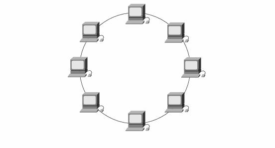
A ring topology is a LAN architecture that consists of a series of devices connected to one another by unidirectional transmission links to form a single closed loop. Both Token Ring/IEEE 802.5 and FDDI networks implement a ring topology.
A star topology is a LAN architecture in which the endpoints on a network are connected to a common central hub, or switch, by dedicated links. Logical bus and ring topologies are often implemented physically in a star topology.
A tree topology is a LAN architecture that is identical to the bus topology, except that branches with multiple nodes are possible in this case.

TYPES OF LAN TECHNOLOGY
ETHERNET:
Ethernet is the most popular physical layer LAN technology in use today. It defines the number of conductors that are required for a connection, the performance thresholds that can be expected, and provides the framework for data transmission. A standard Ethernet network can transmit data at a rate up to 10 Megabits per second (10 Mbps). Other LAN types include Token Ring, Fast Ethernet, Gigabit Ethernet, 10 Gigabit Ethernet, Fiber Distributed Data Interface (FDDI), Asynchronous Transfer Mode (ATM) and Local Talk.
Ethernet is popular because it strikes a good balance between speed, cost and ease of installation. These benefits, combined with wide acceptance in the computer marketplace and the ability to support virtually all popular network protocols, make Ethernet an ideal networking technology for most computer users today.
The Institute for Electrical and Electronic Engineers developed an Ethernet standard known as IEEE Standard 802.3. This standard defines rules for configuring an Ethernet network and also specifies how the elements in an Ethernet network interact with one another. By adhering to the IEEE standard, network equipment and network protocols can communicate efficiently.
FAST ETHERNET:
The Fast Ethernet standard (IEEE 802.3u) has been established for Ethernet networks that need higher transmission speeds. This standard raises the Ethernet speed limit from 10 Mbps to 100 Mbps with only minimal changes to the existing cable structure. Fast Ethernet provides faster throughput for video, multimedia, graphics, Internet surfing and stronger error detection and correction.
There are three types of Fast Ethernet: 100BASE-TX for use with level 5 UTP cable; 100BASE-FX for use with fiber-optic cable; and 100BASE-T4 which utilizes an extra two wires for use with level 3 UTP cable. The 100BASE-TX standard has become the most popular due to its close compatibility with the 10BASE-T Ethernet standard.
GIGABIT ETHERNET:
Gigabit Ethernet was developed to meet the need for faster communication networks with applications such as multimedia and Voice over IP (VoIP). Also known as "gigabit-Ethernet-over-copper" or 1000Base-T, GigE is a version of Ethernet that runs at speeds 10 times faster than 100Base-T. It is defined in the IEEE 802.3 standard and is currently used as an enterprise backbone. Existing Ethernet LANs with 10 and 100 Mbps cards can feed into a Gigabit Ethernet backbone to interconnect high performance switches, routers and servers.
10 GIGABIT ETHERNET:
10 Gigabit Ethernet is the fastest and most recent of the Ethernet standards. IEEE 802.3ae defines a version of Ethernet with a nominal rate of 10Gbits/s that makes it 10 times faster than Gigabit Ethernet.
Unlike other Ethernet systems, 10 Gigabit Ethernet is based entirely on the use of optical fiber connections. This developing standard is moving away from a LAN design that broadcasts to all nodes, toward a system which includes some elements of wide area routing. As it is still very new, which of the standards will gain commercial acceptance has yet to be determined.
TOKEN RING:
Token Ring is another form of network configuration. It differs from Ethernet in that all messages are transferred in one direction along the ring at all times. Token Ring networks sequentially pass a “token” to each connected device. When the token arrives at a particular computer (or device), the recipient is allowed to transmit data onto the network. Since only one device may be transmitting at any given time, no data collisions occur. Access to the network is guaranteed, and time-sensitive applications can be supported. However, these benefits come at a price. Component costs are usually higher, and the networks themselves are considered to be more complex and difficult to implement. Various PC vendors have been proponents of Token Ring networks.
COLLISIONS
Ethernet is a shared media, so there are rules for sending
packets of data to avoid conflicts and protect data integrity. Nodes
determine when the network is available for sending packets. It is possible
that two nodes at different locations attempt to send data at the same time.
When both PCs are transferring a packet to the network at the same time, a
collision will result. This can slow the performance of the network from the
user's point of view. Segmenting the network, where a network is divided
into different pieces joined together logically with a bridge or switch, is
one way of reducing an overcrowded network.
LAN DEVICES
MODEM:
Modem is the short form for modulator-demodulator. A modem is a device or
program that enables a computer to transmit data over, for example, telephone or cable lines. Computer information is stored digitally, whereas information transmitted over telephone lines is transmitted in the form of analog waves. A modem converts between these two forms.
SERVER:
A computer or device is a network that manages network resources. For example, a file server is a computer and storage device dedicated to storing files. Any user on the network can store files on the server. A print server is a computer that manages one or more printers, and a network server is a computer that manages network traffic. A database server is a computer system that processes database queries. Servers are often dedicated, meaning that they perform no other tasks besides their server tasks. On multiprocessing operating systems, however, a single computer can execute several programs at once. A server in this case could refer to the program that is managing resources rather than the entire computer.
UTP:
Short for unshielded twisted pair, a popular type of cable that consists of two unshielded wires twisted around each other. Due to its low cost, UTP cabling is used extensively for local-area networks (LANs) and telephone connections. UTP cabling does not offer as high bandwidth or as good protection from interference as coaxial or fiber optic cables, but it is less expensive and easier to work with.
Cable Grade Capabilities
|
Cable Name |
Makeup |
Frequency Support |
Data Rate |
Network Compatibility |
|
Cat-5 |
4 twisted pairs of copper wire -- terminated by RJ45 connectors |
100 MHz |
Up to 1000Mbps |
ATM, Token Ring,1000Base-T, 100Base-TX, 10Base-T |
|
Cat-5e |
4 twisted pairs of copper wire -- terminated by RJ45 connectors |
100 MHz |
Up to 1000Mbps |
10Base-T, 100Base-TX, 1000Base-T |
|
Cat-6 |
4 twisted pairs of copper wire -- terminated by RJ45 connectors |
250 MHz |
1000Mbps |
10Base-T, 100Base-TX, 1000Base-T |
NETWORK INTERFACE CARDS:
Network Interface Cards, commonly referred to as NICs, and are used to connect a PC to a network. The NIC provides a physical connection between the networking cable and the computer's internal bus. Different computers have different bus architectures. PCI bus slots are most commonly found on 486/Pentium PCs and ISA expansion slots are commonly found on 386 and older PCs. NICs come in three basic varieties: 8-bit, 16-bit, and 32-bit. The larger the number of bits that can be transferred to the NIC, the faster the NIC can transfer data to the network cable. Most NICs are designed for a particular type of network, protocol, and medium, though some can serve multiple networks.
Many NIC adapters comply with plug-and-play specifications. On these systems, NICs are automatically configured without user intervention, while on non-plug-and-play systems, configuration is done manually through a set-up program and/or DIP switches.
Cards are available to support almost all networking standards. Fast Ethernet NICs are often 10/100 capable, and will automatically set to the appropriate speed. Gigabit Ethernet NICs are 10/100/1000 capable with auto negotiation depending on the user’s Ethernet speed. Full duplex networking is another option where a dedicated connection to a switch allows a NIC to operate at twice the speed.
ETHERNET SWITCHES:
LAN switches link multiple networks together and have two basic architectures: cut-through and store-and-forward. In the past, cut-through switches were faster because they examined the packet destination address only before forwarding it on to its destination segment. A store-and-forward switch works like a bridge in that it accepts and analyzes the entire packet before forwarding it to its destination.
Both cut-through and store-and-forward switches separate a network into collision domains, allowing network design rules to be extended. Each of the segments attached to an Ethernet switch has a full 10 Mbps of bandwidth shared by fewer users, which results in better performance (as opposed to hubs that only allow bandwidth sharing from a single Ethernet). Newer switches today offer high-speed links, either Fast Ethernet, Gigabit Ethernet, 10 Gigabit Ethernet or ATM. These are used to link switches together or give added bandwidth to high-traffic servers
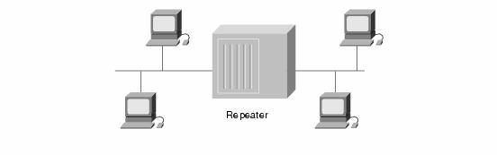
REPEATERS:
A repeater is a physical layer device used to interconnect the media segments of an extended network. A repeater essentially enables a series of cable segments to be treated as a single cable. Repeaters receive signals from one network segment and amplify, retime, and retransmit those signals to another network segment. These actions prevent signal deterioration caused by long cable lengths and large numbers of connected devices. Repeaters are incapable of performing complex filtering and other traffic processing. In addition, all electrical signals, including electrical disturbances and other errors, are repeated and amplified.
HUB:
A hub is a physical layer device that connects multiple user stations, each via a dedicated cable. Electrical interconnections are established inside the hub. Hubs are used to create a physical star network while maintaining the logical bus or ring configuration of the LAN. In some respects, a hub functions as a multiport repeater.
BRIDGES:
Bridges connect two LAN segments of similar or dissimilar types, such as Ethernet and Token Ring. This allows two Ethernet segments to behave like a single Ethernet allowing any pair of computers on the extended Ethernet to communicate. Bridges are transparent therefore computers don’t know whether a bridge separates them.
ROUTER:
A router is a device that forwards data packets along networks, and determines which way to send each data packet based on its current understanding of the state of its connected networks. Routers are typically connected to at least two networks, commonly two LANs or WANs or a LAN and its Internet Service Provider’s (ISPs) network. Routers are located at gateways, the places where two or more networks connect.
Routers filter out network traffic by specific protocol rather than by packet address. Routers also divide networks logically instead of physically. An IP router can divide a network into various subnets so that only traffic destined for particular IP addresses can pass between segments. Network speed often decreases due to this type of intelligent forwarding. Such filtering takes more time than that exercised in a switch or bridge, which only looks at the Ethernet address. However, in more complex networks, overall efficiency is improved by using routers.
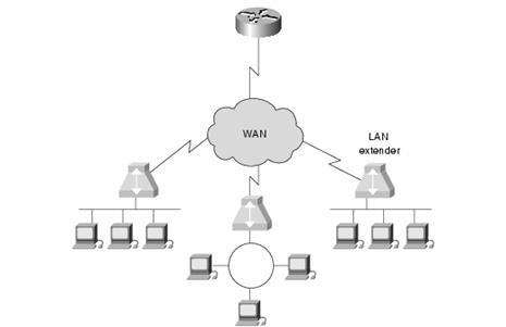
LAN EXTENDER:
A LAN extender is a remote-access multilayer switch that connects to a host router. LAN extenders forward traffic from all the standard network layer protocols (such as IP, IPX, and AppleTalk) and filter traffic based on the MAC address or network layer protocol type. LAN extenders scale well because the host router filters out unwanted broadcasts and multicasts. However, LAN extenders are not capable of segmenting traffic or creating security firewalls.
ACHIEVEMENTS
The main achievements of the training at Indian Railways are that we got familiar with the latest technologies and principles of networking. The main achievement could be said to get knowledge about recent technologies of LAN. We got experience as to how to organize the things. After the completion of the training we consider ourselves capable of facing any other challenge of that type. The training at Indian Railways cultivated the zeal of inquisitiveness and the excitement to know more than more about this field in limited duration.
CONCLUSION
Indian Railways, as an organization is a very vast center of telecommunication in itself. Today the telecommunicating world is getting it’s roots, grabbing the new era more firmly. We think that our training was an success and we think that Indian Railways was an excellent training institute for inquisitive emerging engineers. In Indian Railways, training is given to engineering aspirant desiring to secure future in the dynamic world of Telecommunication.
BIBLIOGRAPHY
6. “Computer Networks” by” Tenin Baum
Contribute content or training
reports / feedback / Comments
Practical
Training reports
All rights reserved © copyright
123ENG