Argumented Reality Report
Augmented Reality
Introduction
Augmented Reality (AR) is a growing area in virtual reality research. The world environment around us provides a wealth of information that is difficult to duplicate in a computer. This is evidenced by the worlds used in virtual environments. Either these worlds are very simplistic such as the environments created for immersive entertainment and games, or the system that can create a more realistic environment has a million dollar price tag such as flight simulators. An augmented reality system generates a composite view for the user. It is a combination of the real scene viewed by the user and a virtual scene generated by the computer that augments the scene with additional information. Augmented reality presented to the user enhances that person's performance in and perception of the world. The ultimate goal is to create a system such that the user cannot tell the difference between the real world and the virtual augmentation of it. To the user of this ultimate system it would appear that he is looking at a single real scene.
Augmented Reality vs. Virtual Reality
Virtual reality is a technology that encompasses a broad spectrum of ideas. The term is defined as "a computer generated, interactive, three-dimensional environment in which a person is immersed. There are three key points in this definition. First, this virtual environment is a computer generated three-dimensional scene, which requires high performance computer graphics to provide an adequate level of realism. The second point is that the virtual world is interactive. A user requires real-time response from the system to be able to interact with it in an effective manner. The last point is that the user is immersed in this virtual environment. One of the identifying marks of a virtual reality system is the head mounted display worn by users. These displays block out all the external world and present to the wearer a view that is under the complete control of the computer. The user is completely immersed in an artificial world and becomes divorced from the real environment. For this immersion to appear realistic the virtual reality system must accurately sense how the user is moving and determine what effect that will have on the scene being rendered in the head mounted display.
The discussion above highlights the similarities and differences between virtual reality and augmented reality systems. A very visible difference between these two types of systems is the immersiveness of the system. Virtual reality strives for a totally immersive environment. In contrast, an augmented reality system is augmenting the real world scene necessitating that the user maintains a sense of presence in that world. The virtual images are merged with the real view to create the augmented display. There must be a mechanism to combine the real and virtual that is not present in other virtual reality work. The computer generated virtual objects must be accurately registered with the real world in all dimensions. Errors in this registration will prevent the user from seeing the real and virtual images as fused. The correct registration must also be maintained while the user moves about within the real environment. Discrepancies or changes in the apparent registration will range from distracting which makes working with the augmented view more difficult, to physically disturbing for the user making the system completely unusable. An immersive virtual reality system must maintain registration so that changes in the rendered scene match with the perceptions of the user. Milgram defines the Reality-Virtuality continuum shown as Figure 1.
Figure 1 - Milgram's Reality-Virtuality Continuum
The real world and a totally virtual environment are at the two ends of this continuum with the middle region called Mixed Reality. Augmented reality lies near the real world end of the line with the predominate perception being the real world augmented by computer generated data. Augmented Virtuality is a term created by Milgram to identify systems, which are mostly synthetic with some real world imagery added such as texture mapping video onto virtual objects. This is a distinction that will fade as the technology improves and the virtual elements in the scene become less distinguishable from the real ones.
Video Merging
The task in the augmented reality system is to register the virtual frame of reference with what the user is seeing. Registration is more critical in an augmented reality system because we are more sensitive to visual misalignments than to the type of vision-kinesthetic errors that might result in a standard virtual reality system. Figure shows the multiple reference frames that must be related in an augmented reality system.
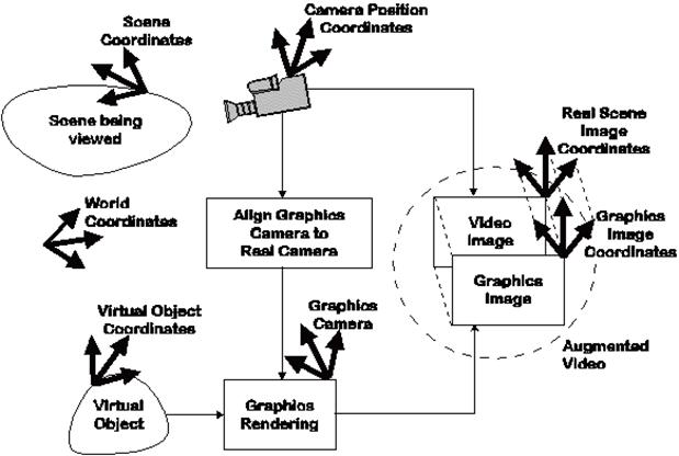 The
scene is viewed by an imaging device, which in this case is depicted
as a video camera. The camera performs a perspective projection of
the 3D world onto a 2D image plane. The generation of the virtual
image is done with a standard computer graphics system. The virtual
objects are modeled in an object reference frame. The graphics
system requires information about the imaging of the real scene so
that it can correctly render these objects. This data will control
the synthetic camera that is used to generate the image of the
virtual objects. This image is then merged with the image of the
real scene to form the augmented reality image.
The
scene is viewed by an imaging device, which in this case is depicted
as a video camera. The camera performs a perspective projection of
the 3D world onto a 2D image plane. The generation of the virtual
image is done with a standard computer graphics system. The virtual
objects are modeled in an object reference frame. The graphics
system requires information about the imaging of the real scene so
that it can correctly render these objects. This data will control
the synthetic camera that is used to generate the image of the
virtual objects. This image is then merged with the image of the
real scene to form the augmented reality image.
Components of Augmented Reality System
1. Head Mounted Display
2. Tracking System (GPS)
3. Mobile Computing Power
Head Mounted Displays
They enable us to view graphics and text created by the augmented reality system. There are two basic types of head mounted displays being used.
1. Video See-Through Display
The "see-through" designation comes from the need for the user to be able to see the real worldview that is immediately in front of him even when wearing the HMD. This system blocks the wearers surrounding environment using small cameras attached to the outside of the goggle to capture images. On the inside of the display, the video image is played in real-time and the graphics are superimposed on the video. One problem with the use of video cameras is that there is more lag, meaning that there is a delay in image-adjustment when the viewer moves his or her head.
Video See-through Display
The head position obtained through the video camera by the process as explained above is the input to the graphics system. Graphics System produces the virtual objects, which are aligned to that of real objects, virtual objects are then merged with the real objects generated by the video camera and sent to the monitor from where it is displayed to the user.
2.Optical See-Through Displays
The optical see-through HMD eliminates the video channel that is looking at the real scene. Instead merging of real world and virtual augmentation is done optically in front of the user.
Optical See-Through Display
There are advantages and disadvantages to each of these types of displays. With both of the displays that use a video camera to view the real world there is a forced delay of up to one frame time to perform the video merging operation. At standard frame rates that will be potentially a 33.33 millisecond delay in the view seen by the user. Since everything the user sees is under system control compensation for this delay could be made by correctly timing the other paths in the system. Or, alternatively, if other paths are slower then the video of the real scene could be delayed. With an optical see-through display the view of the real world is instantaneous so it is not possible to compensate for system delays in other areas. On the other hand, with monitor based and video see-through displays a video camera is viewing the real scene. An advantage of this is that the image generated by the camera is available to the system to provide tracking information. The optical see-through display does not have this additional information. The only position information available with that display is what position sensors on the head can provide mounted display itself. The major advantage of optical see through display is that they could be made very small however the biggest constraint in using this technology is the prohibitive cost.
The main components of our system are a backpack computer (with 3D graphics acceleration), a differential GPS system, a head-worn display interface (with orientation tracker), and a spread spectrum radio communication link, all attached to the backpack

The above shown figure is the block diagram of AR system. It consists of a backup PC to which two inputs one from the GPS receiver and other from the head mounted display comes. The signal from the GPS receiver tells the co-ordinates of the person and the orientation tracker gives the orientation of the head. These two inputs will be transferred through the satellite to the database server. This server based according to the information received sends the related database to the satellite, which is then transmitted to the backpack PC. The graphics card will generate the virtual objects, which are then merged with the real environment by the head worn display interface and displayed to the user.
Our Research
The discipline
of
affective computing studies how computers can recognize,
understand, and mimic human emotions. Now, in most cyberpunk stories
where humans merge their minds with computers, the computer is able
to interpret the symbolic thinking of its human companion, and
insert symbolic ideas back into the human brain. But wouldn't it be
better if the computer could interpret our values instead?
In fact, it would probably be far easier for computers to learn to
recognize what we like, dislike, approve of or are uncomfortable
with--these base responses tend to be similar between people, and
even across cultural and linguistic barriers. While each of us
probably has a unique encoding for the concept "carrot" in our
brains, we almost certainly share a basic neural and physiological
response when asked whether we like carrots. I.e. you can
teach a computer to recognize that someone is enjoying the carrot
they're munching--but probably you can't teach the computer to
recognize when someone is thinking about carrots.
Basically it's just that the internet is so full of information, we end up spending most of our time filtering out the irrelevant data. If you think about it, like/dislike is the basic crap filter--a computer that could tell you hated pop-up browser ads without being asked would be a good thing.
Looking not too far in the future, we see a world where everybody is immersed in one form or another of augmented reality. Everywhere we look, we see annotations on reality, provided by our AR glasses. The issue then becomes the same as the one we face with the Internet today: how to filter out all the crap?
This is where the values-driven interface becomes crucial. Our AR system needs to be able to recognize our reactions to the various cues, annotations, pop-ups, overlays, sims, and pointers. If our system can do this, it can edit out the things we don't want to see.
e.g. Orthodox religious types no longer see ads for girlie shows or salacious lingerie models on billboards; serious rationalists no longer see the corner church as they walk by. Something else replaces it, a soothing image of the Gandhiji or something... The point is, the augmented world reflects the values of whoever is using it, and it does so seamlessly and automatically.


We introduce a hand held PC in the basic AR diagram. This handheld PC has been specifically trained by the users to understand his likes and dislikes. Now the Back Pack pc will receive input not only from GPS and orientation tracker but also from the hand held PC. Now according to this information it would be decided which data has to be accessed. e.g. if the person is in front of a real object which he hated to see, this information will be conveyed by the handheld pc to the back pack pc which in turn will generate virtual objects so to superimpose the real object the user hates. Thus filtering all the irrelevant information for the user and helping him.
GLOBAL POSITIONING SYSTEM
Where am I? The
question seems simple; the answer, historically, has proved not to
be. For centuries, navigators and explorers have searched the
heavens for a system that would enable them to locate their position
on the globe with the accuracy necessary to avoid tragedy and to
reach their intended destinations. On June 26, 1993, however, the
answer became as simple as the question. On that date, the
U.S. Air Force
launched the
24th Navstar satellite
into orbit, completing a network of 24 satellites known as the
Global Positioning System,
or GPS. With a GPS receiver that costs less than a few hundred
dollars you can instantly learn your location on the planet--your
latitude, longitude,
and even altitude--to within a few hundred feet.
This incredible new technology was made possible
by a combination of scientific and engineering advances,
particularly development of the world's most accurate timepieces:
atomic clocks
that are precise to within a billionth of a second. The clocks were
created by physicists seeking answers to questions about the nature
of the universe, with no conception that their technology would some
day lead to a global system of navigation. Today, GPS is saving
lives, helping society in countless other ways, and generating
100,000 jobs in a multi-billion-dollar industry. It provides a
dramatic
example
of how science works and how basic
GPS SYSTEM SEGMENTS
The GPS consists of three major segments: SPACE, CONTROL and USER.
1.SPACE SEGMENT
The SPACE segment consists of 24 operational satellites in six orbital planes (four satellites in each plane). The satellites operate in circular 20,200 km orbits at an inclination angle of 55 degrees and with a 12-hour period. The position is therefore the same at the same sidereal time each day, i.e. the satellites appear 4 minutes earlier each day.
2.CONTROL SEGMENT
The CONTROL segment consists of five Monitor Stations (Hawaii, Kwajalein, Ascension Island, Diego Garcia, Colorado Springs), three Ground Antennas, (Ascension Island, Diego Garcia, Kwajalein), and a Master Control Station (MCS) located at Schriever AFB in Colorado. The monitor stations passively track all satellites in view, accumulating ranging data. This information is processed at the MCS to determine satellite orbits and to update each satellite's navigation message. Updated information is transmitted to each satellite via the Ground Antennas.
3.USER SEGMENT
The USER segment consists of antennas and receiver-processors that provide positionin research leads to technologies that were virtually unimaginable at the time the research was done.
HOW GPS WORKS
- The basis of GPS is "triangulation" from satellites.
- To "triangulate," a GPS receiver measures distance using the travel time of radio signals.
- To measure travel time, GPS needs very accurate timing, which it achieves with some tricks.
- Along with distance, we need to know exactly where the satellites are in space. High orbits and careful monitoring are the secret.
- Finally you must correct for any delays the signal experiences as it travels through the atmosphere.
Triangulation from Satellites:
Suppose we measure our distance from a satellite and find it to be 11,000 miles. Knowing that we're 11,000 miles from a particular satellite narrows down all the possible locations we could be in the whole universe to the surface of a sphere that is centered on this satellite and has a radius of 11,000 miles. Next, say we measure our distance to a second satellite and find out that it's 12,000 miles away. That tells us that we're not only on the first sphere but we're also on a sphere that's 12,000 miles from the second satellite. Or in other words, we're somewhere on the circle where these two spheres intersect. If we then make a measurement from a third satellite and find that we're 13,000 miles from that one, that narrows our position down even further, to the two points where the 13,000 mile sphere cuts through the circle that's the intersection of the first two spheres. So by ranging from three satellites we can narrow our position to just two points in space.
To decide which one is our true location we could make a fourth measurement. But usually one of the two points is a ridiculous answer (either too far from Earth or moving at an impossible velocity) and can be rejected without a measurement.
Measuring distance from satellite:
The basic problem is in finding the distance of the user from the four satellites. This can be done if we know the time taken by the signal from the satellite to reach to the receiver. Then the total distance is given by
DISTANCE (between the satellite and the user) = TIME (taken by the signal to reach earth)* SPEED (of the signal which is the speed of light).
The time taken by the signal to reach from satellite to the receiver can be found by calculating the phase shift of the Pseudo Random Code
Pseudo Random Code:
The Pseudo
Random Code is a fundamental part of GPS. Physically it's just a
very complicated digital code, or in other words, a complicated
sequence of "on" and "off" pulses. The
signal is so
complicated that it almost looks like random electrical noise. Hence
the name "Pseudo-Random." There are several good reasons for that
complexity: First, the complex pattern helps make sure that the
receiver doesn't accidentally sync up to some other signal. The
patterns are so complex that it's highly unlikely that a stray
signal will have exactly the same shape. Since each satellite has
its own unique Pseudo-Random Code this complexity also guarantees
that the receiver won't accidentally pick up another satellite's
signal. So all the satellites can use the same frequency without
jamming each other. And it makes it more difficult for a hostile
force to jam the system. We assume that both the satellite and the
receiver start generating their codes at exactly the same time.
Distance to a satellite is determined by measuring how long a radio
signal takes to reach us from that satellite.
-
To make the
measurement we assume that both the satellite and our receiver are
generating the same pseudo-random codes at exactly the same time.
-
By comparing
how late the satellite's pseudo-random code appears compared to
our receiver's code, we determine how long it took to reach us.
- Multiply that travel time by the speed of light and you've got distance.
But how do we make sure everybody is perfectly synchronized?
If measuring the travel time of a radio signal is the key to GPS, then our stop watches had better be darn good, because if their timing is off by just a thousandth of a second, at the speed of light, that translates into almost 200 miles of error!
On the satellite side, timing is almost perfect because they have incredibly precise atomic clocks on board.
Atomic clocks don't run on atomic energy. They get the name because they use the oscillations of a particular atom as their "metronome." This form of timing is the most stable and accurate reference man has ever developed.
Remember that both the satellite and the receiver need to be able to precisely synchronize their pseudo-random codes to make the system work. Our receivers needed atomic clocks (which costs a lot) nobody could afford it. The secret to perfect timing is to make an extra satellite measurement. If our receiver's clocks were perfect, then all our satellite ranges would intersect at a single point (which is our position). But with imperfect clocks, a fourth measurement, done as a crosscheck, will NOT intersect with the first three. Since any offset from universal time will affect all of our measurements, the receiver looks for a single correction factor that it can subtract from all its timing measurements that would cause them all to intersect at a single point. That correction brings the receiver's clock back into sync with universal time . Once it has that correction it applies to all the rest of its measurements and now we've got precise position of accuracy upto 3-6 mts.
Precise Positioning Service (PPS)
- Authorized users with cryptographic equipment and keys and specially equipped receivers use the Precise Positioning System. U. S. and Allied military, certain U.S Government agencies, and selected civil users specifically approved by the U.S. Government, can use the PPS.
-
PPS
Predictable Accuracy
- 22 meter Horizontal accuracy
- 27.7 meter vertical accuracy
Standard Positioning Service (SPS)
- Civil users worldwide use the SPS without charge or restrictions. Most receivers are capable of receiving and using the SPS signal. The SPS accuracy is intentionally degraded by the DOD by the use of Selective Availability.
-
SPS
Predictable Accuracy
- 100 meter horizontal accuracy
- 156 meter vertical accuracy
GPS Satellite Signals
- The SVs transmit two microwave carrier signals. The L1 frequency (1575.42 MHz) carries the navigation message and the SPS code signals. The L2 frequency (1227.60 MHz) is used to measure the ionospheric delay by PPS equipped receivers.
-
Three binary
codes shift the L1 and/or L2 carrier phase.
- The C/A Code (Coarse Acquisition) modulates the L1 carrier phase. The C/A code is a repeating 1 MHz Pseudo Random Noise (PRN) Code. This noise-like code modulates the L1 carrier signal, "spreading" the spectrum over a 1 MHz bandwidth. The C/A code repeats every 1023 bits (one millisecond). There is a different C/A code PRN for each SV. GPS satellites are often identified by their PRN number, the unique identifier for each pseudo-random-noise code. The C/A code that modulates the L1 carrier is the basis for the civil SPS.
- The P-Code (Precise) modulates both the L1 and L2 carrier phases. The P-Code is a very long (seven days) 10 MHz PRN. The P-Code is encrypted into the Y-Code. The encrypted Y-Code requires a classified AS Module for each receiver channel and is for use only by authorized users with cryptographic keys. The P (Y)-Code is the basis for the PPS.
- The Navigation Message also modulates the L1-C/A code signal. The Navigation Message is a 50 Hz signal consisting of data bits that describe the GPS satellite orbits, clock corrections, and other system parameters.
GPS Data
- The GPS Navigation Message consists of time-tagged data bits marking the time of transmission of each sub frame at the time they are transmitted by the SV. A data bit frame consists of 1500 bits divided into five 300-bit sub frames. A data frame is transmitted every thirty seconds. Three six-second sub frames contain orbital and clock data. SV Clock corrections are sent in sub frame one and precise SV orbital data sets (ephemeris data parameters) for the transmitting SV are sent in sub frames two and three. Sub frames four and five are used to transmit different pages of system data. An entire set of twenty-five frames (125 sub frames) makes up the complete Navigation Message that is sent over a 12.5 minute period.
- Data frames (1500 bits) are sent every thirty seconds. Each frame consists of five sub frames.
- Data bit sub frames (300 bits transmitted over six seconds) contain parity bits that allow for data checking and limited error correction
Factors affecting GPS signals:
1.Ionosphere and Troposphere delays: The signal from the satellite slows down while passing through the ionosphere and troposphere before reaching the receiver. GPS system uses an inbuilt model that calculates the average amount of delay.
2. Signal and Multipath: While coming from the satellite signal may get reflected of by high buildings or some other objects before it reaches the receiver. Thus causing an extra timing error.
3. Orbital Errors: These errors are also known as ephemeris error. These are the inaccuracy of satellites while orbiting the earth.
4. Receiver Clock errors: As we use an ordinary quartz clock in the GPS receiver it introduces certain timing errors.
Geometric Dilution of Precision (GDOP):
There are usually more satellites available than a receiver need to fix a position so the receiver picks a few and ignores the rest. These picks should be as far from each other in the space as possible as for maximum accuracy the spheres should intersect at almost right angles.
The accuracy achieved by this GPS system is 3-6 mts. but for Augmented Reality accuracy in centimeters is required. For that purpose we use Differential GPS Systems.
Differential GPS Systems:
It is a way to correct various inaccuracies. It involves the co-operation of two receivers out of which one is stationary and the other one is with the user. The stationary receiver ties all the satellite measurements into a solid local reference. The reference receiver is put onto a point that has been very accurately surveyed. It receives the GPS signal and works in reverse order that is instead of using timing signal to calculate the position, It uses the known position to calculate the time and then compare it with the actual time that the signal must have taken from the satellite to reach the receiver. This error information is then transferred to the roving receiver. At a particular moment the stationary receiver doesn’t know which satellites are being used by the roving receiver. So it calculates the timing error from all the 24 satellites and sends this information to the roving one. The roving receiver then uses the required information to calculate the correction factor and neglect the rest of information.
Mobile Computing Power
This is the component of the AR system, which generates all the virtual objects and merges the real based environment with the virtual objects. It is a communicator between the AR system and the database server.
APPLICATIONS DOMAINS OF AR SYSTEM
1. Entertainment
A simple form of augmented reality has been in use in the entertainment and news business for quite some time. Whenever you are watching the evening weather report the weather reporter is shown standing in front of changing weather maps. In the studio the reporter is actually standing in front of a blue or green screen. This real image is augmented with computer-generated maps using a technique called chroma keying.
2. Military Training
The military has been using displays in cockpits that present information to the pilot on the windshield of the cockpit or the visor of their flight helmet. This is a form of augmented reality display. SIMNET, a distributed war games simulation system, is also embracing augmented reality technology. By equipping military personnel with helmet mounted visor displays or a special purpose rangefinder the activities of other units participating in the exercise can be imaged. While looking at the horizon, for example, the display-equipped soldier could see a helicopter rising above the tree line. This helicopter could be being flown in simulation by another participant. In wartime, the display of the real battlefield scene could be augmented with annotation information or highlighting to emphasize hidden enemy units.
3. Engineering Design
Imagine that a group of designers are working on the model of a complex device for their clients. The designers and clients want to do a joint design review even though they are physically separated. If each of them had a conference room that was equipped with an augmented reality display this could be accomplished. The physical prototype that the designers have mocked up is imaged and displayed in the client's conference room in 3D. The clients can walk around the display looking at different aspects of it. To hold discussions the client can point at the prototype to highlight sections and this will be reflected on the real model in the augmented display that the designers are using. Or perhaps in an earlier stage of the design, before a prototype is built, the view in each conference room is augmented with a computer-generated image of the current design built from the CAD files describing it. This would allow real time interaction with elements of the design so that either side can make adjustments and changes that are reflected in the view seen by both groups.
4.Manufacturing, Maintenance and Repair
When the maintenance technician approaches a new or unfamiliar piece of equipment instead of opening several repair manuals they could put on an augmented reality display. In this display the image of the equipment would be augmented with annotations and information pertinent to the repair. For example, the location of fasteners and attachment hardware that must be removed would be highlighted. Then the inside view of the machine would highlight the boards that need to be replaced worn by personnel that is attached to an optical see-through display The wireless connection allows the soldier to access repair manuals and images of the equipment. Future versions might register those images on the live scene and provide animation to show the procedures that must be performed.
5. Consumer Design
Virtual reality systems are already used for consumer design. Using perhaps more of a graphics system than virtual reality, when you go to the typical home store wanting to add a new deck to your house, they will show you a graphical picture of what the deck will look like. It is conceivable that a future system would allow you to bring a video tape of your house shot from various viewpoints in your backyard and in real time it would augment that view to show the new deck in its finished form attached to our house. Or bring in a tape of your current kitchen and the augmented reality processor would replace your current kitchen cabinetry with virtual images of the new kitchen that you are designing.
Applications in the fashion and beauty industry that would benefit from an augmented reality system can also be imagined. If the dress store does not have a particular style dress in your size an appropriate sized dress could be used to augment the image of you. As you looked in the three-sided mirror you would see the image of the new dress on your body. Changes in hem length, shoulder styles or other particulars of the design could be viewed on you before you place the order. When you head into some high-tech beauty shops today you can see what a new hairstyle would look like on a digitized image of yourself. But with an advanced augmented reality system you would be able to see the view as you moved. If the dynamics of hair were included in the description of the virtual object you would also see the motion of your hair as your head moved
6.Instant information
Tourists and students could use these systems to learn more about a certain historical event. Imagine walking onto a Civil War battlefield and seeing a re-creation of historical events on a head-mounted, augmented-reality display. It would immerse you in the event, and the view would be panoramic.
7.Gaming
How cool would it be to take video games outside? The game could be projected onto the real world around you, and you could, literally, be in it as one of the characters. When one uses this system, the game surrounds him as he walks across campus.
There are hundreds of potential applications for such a technology, gaming and entertainment being the most obvious ones. Any system that gives people instant information, requiring no research on their part, is bound to be a valuable to anyone in pretty much any field. Augmented-reality systems will instantly recognize what someone is looking at, and retrieve and display the data related to that view.
Performance issues of augmented reality system
Augmented reality systems are expected to run in real-time so that a user will be able to move about freely within the scene and see a properly rendered augmented image. This places two performance criteria on the system. They are:
- Update rate for generating the augmenting image,
- Accuracy of the registration of the real and virtual image.
Visually the real-time constraint is manifested in the user viewing an augmented image in which the virtual parts are rendered without any visible jumps. To appear without any jumps, a standard rule of thumb is that the graphics system must be able to render the virtual scene at least 10 times per second. This is well within the capabilities of current graphics systems for simple to moderate graphics scenes. For the virtual objects to realistically appear part of the scene more photorealistic graphics rendering is required. The current graphics technology does not support fully lit, shaded and ray-traced images of complex scenes. Fortunately, there are many applications for augmented reality in which the virtual part is either not very complex or will not require a high level of photorealism.
Failures in the second performance criterion have two possible causes. One is a misregistration of the real and virtual scene because of noise in the system. The position and pose of the camera with respect to the real scene must be sensed. Any noise in this measurement has the potential to be exhibited as errors in the registration of the virtual image with the image of the real scene. Fluctuations of values while the system is running will cause jittering in the viewed image. As mentioned previously, our visual system is very sensitive to visual errors, which in this case would be the perception that the virtual object is not stationary in the real scene or is incorrectly positioned. Misregistrations of even a pixel can be detected under the right conditions. The second cause of misregistration is time delays in the system. As mentioned in the previous paragraph, a minimum cycle time of 0.1 seconds is needed for acceptable real-time performance. If there are delays in calculating the camera position or the correct alignment of the graphics camera then the augmented objects will tend to lag behind motions in the real scene. The system design should minimize the delays to keep overall system delay within the requirements for real-time performance.
Summary
Though Augmented Reality is in a nascent stage and is still not being used in mass. We feel that with the growing research in AR and shrinking size and complexity of AR system it is not far away in time where everybody will own his own AR system
Contribute content or training
reports / feedback / Comments
Practical
Training reports
All rights reserved © copyright
123ENG